Part 3: The Electronics Package
I talked a bit about the process of building the shell in part 2. Now it’s time to figure out what goes inside it — the electronics.
1. Rough Plan Outline Link to heading
I spent a lot of time before beginning this project thinking about the way I wanted to light it. The images of Daft Punk from the early 2000s and Bangalter’s glowing lights immediately came to mind. Over the years I have seen other people recreate this helmet with varying degrees of polish and sophistication. The ones that went all the way were usually soldering loose LEDs together and multiplexing with Arduinos and big bundles of wire. And I don’t think I saw any that allowed the helmet to talk to other devices. That left me with a few ideas to work with.
Design Constraints & Must-Haves Link to heading
I generally knew a few things needed to be true for this to work:
- The LED grid needed to be modular, minimize loose wires, and be easy to see through.
- It needed to be 8 rows tall and 32 columns wide.
- The controller needed to be able to drive the display and negotiate communication with other devices, ideally without wires.
- It couldn’t be heavy — it’s something that needs to be worn.
2. Component Choice Link to heading
This part of the planning was the simplest in hindsight but the hardest for me to get started. I don’t know why, but I found it daunting.
Shift Registers & Multiplexing Link to heading
Driving 256 LEDs independently at a refresh rate fast enough to fool the eye is more than you want to throw at GPIO pins directly. The standard solution is multiplexing: illuminate one row at a time, in rapid sequence. Each row gets its column data, stays lit for a brief window, and then hands off to the next. Human persistence of vision does the rest — what looks like a continuous image is actually a high-frequency strobe, the same trick used in every TV and monitor you’ve ever looked at.
In this project, the microcontroller has three primary responsibilities:
- Shift column data out to each row’s driver ICs
- Enable each row in sequence to build a visible frame
- Manage incoming frame data in the background without disturbing the display
For column data storage, I used a daisy-chain of 4 shift registers per row, giving 32 bits of column data per row. By tying the serial clock, data, and latch lines together across all 8 rows and keeping the output-enable lines independent, I can drive the entire 8×32 matrix with just a handful of MCU pins.
I settled on the Raspberry Pi Pico W for the MCU, and the TI TLC6C598 shift register LED driver for the column ICs — 8 rows of 4 ICs each, 32 total. The TLC6C598 is an 8-bit serial-in, parallel-out shift register with a built-in output latch and an active-low output enable, which maps cleanly onto exactly what this circuit needs.
3. Schematic and PCB Layout Link to heading
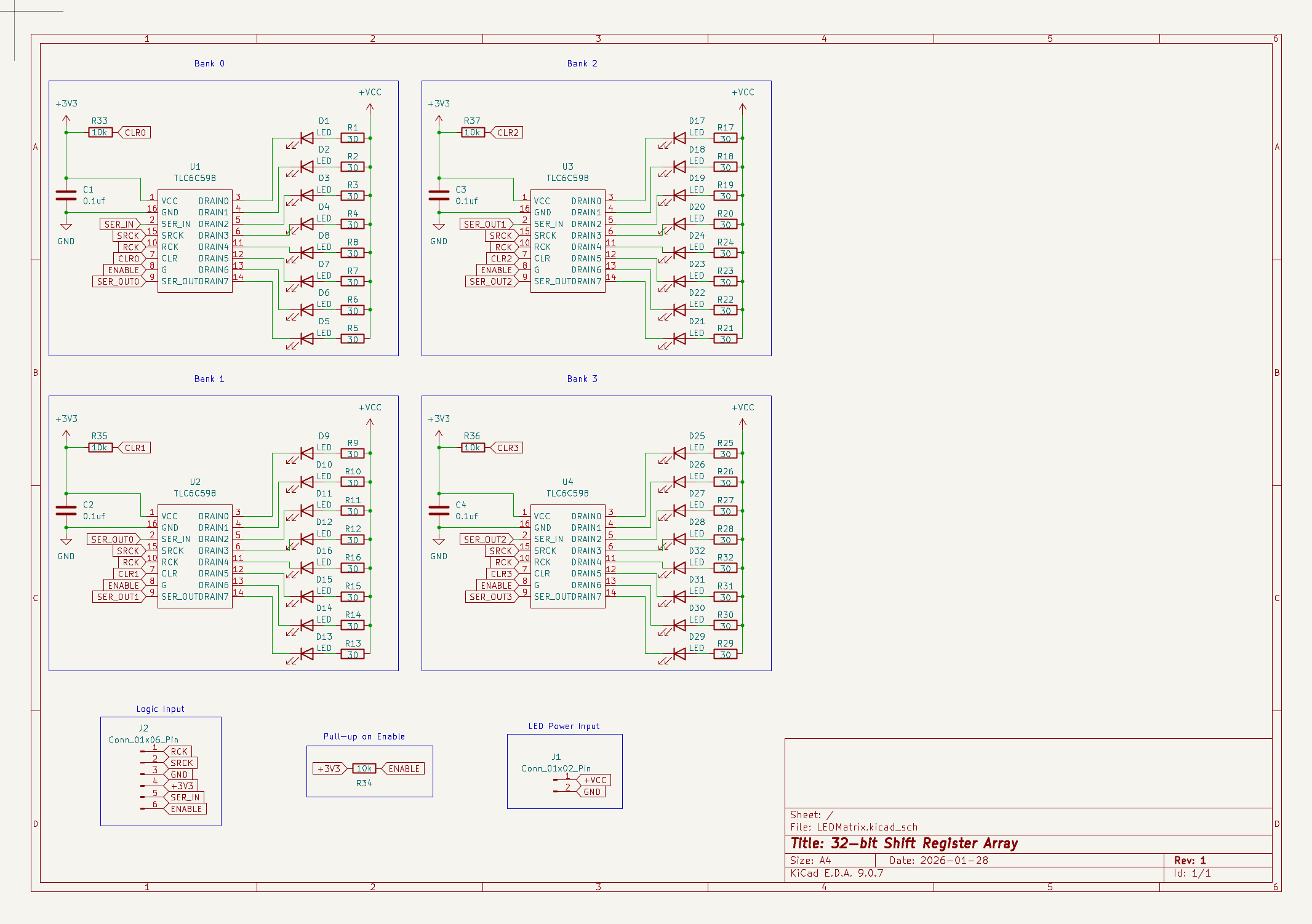
Signal Path Link to heading
The TLC6C598s communicate over a standard serial interface: a clock line (SCK), a data line (SER_IN), and a latch line (RCK). Four ICs are chained in series on each row board, so 32 bits of column data get shifted in over 32 clock pulses. When the last bit is in place, a rising edge on RCK latches all 32 outputs simultaneously — the whole row switches at once rather than rippling bit by bit. The SCK, SER_IN, and RCK lines are shared across all 8 row boards as a bus. Each row also has its own output-enable (OE) line running back to the Pico, which is how the multiplexing actually works: only one row’s OE is asserted at a time, regardless of what data the others are holding.
Pull-Up Resistors Link to heading
The OE pin is active-low, meaning the row is enabled when OE is pulled to ground and disabled when it’s high. That’s actually the safer default — if the Pico’s GPIO is ever in a floating or high-impedance state during boot or power transitions, a 10k pull-up to VCC ensures the row stays off. Accidentally illuminating all 32 LEDs in a row at full current during startup is exactly the kind of thing that stresses a chip unnecessarily.
The TLC6C598 also has a CLR pin that resets all outputs to zero when asserted. That would be a problem mid-operation if anything ever glitched it low, so I tied it directly to VCC to permanently disable it.
Capacitors Link to heading
Each TLC6C598 switches up to 8 outputs simultaneously, which causes brief current spikes on the power rail — the inductance of even short PCB traces resists instantaneous current changes, causing voltage to droop and then ring back. Without local decoupling, those spikes can couple into adjacent signal lines and cause glitching. A 100nF ceramic capacitor placed close to each IC’s VCC and GND pins gives those spikes a low-impedance path to dissipate before they travel further down the rail. Four ICs per board means four capacitors per board.
Current Constraints Link to heading
The TLC6C598 appears to be designed with automotive applications in mind — it handles much higher voltages than I ever expect to need. But its per-output current sink limit is around 50 mA, which at first glance sounds like plenty. The issue is that with 256 outputs across 32 ICs, the aggregate current through the system adds up quickly if you’re not careful about how you drive the LEDs. I was targeting around 5–10 mA per LED under normal operation, so I chose 30Ω current-limiting resistors to land in that range at the supply voltage I was planning to use.
Total Power Link to heading
This is where multiplexing becomes useful beyond just the pin count. Because only one row is active at a time, each LED only conducts for 1/8th of each frame period — a 12.5% duty cycle. That means the average current through any given LED is a fraction of its peak current, and the heat generated by the ICs stays proportional to that average rather than the peak. In practice, each row drew around 150 mA at full brightness during testing. Spread across 8 rows at 1/8 duty cycle, the average system draw at full brightness comes in at around 1.2 Amps — much more manageable for a battery-powered device.
Interfacing Link to heading
I went with JST-PH connectors because they’re ubiquitous, cheap, and rated for the current levels involved. To keep the overall stack as thin as possible, I used right-angle (90°) connectors so the mating direction is parallel to the board surface. Each row board has a 6-pin logic connector on one side — carrying SCK, SER_IN, RCK, OE, VCC, and GND — and a 2-pin power connector on the other for the LED supply rail, which I kept separate from the logic supply to avoid noise coupling between the two.
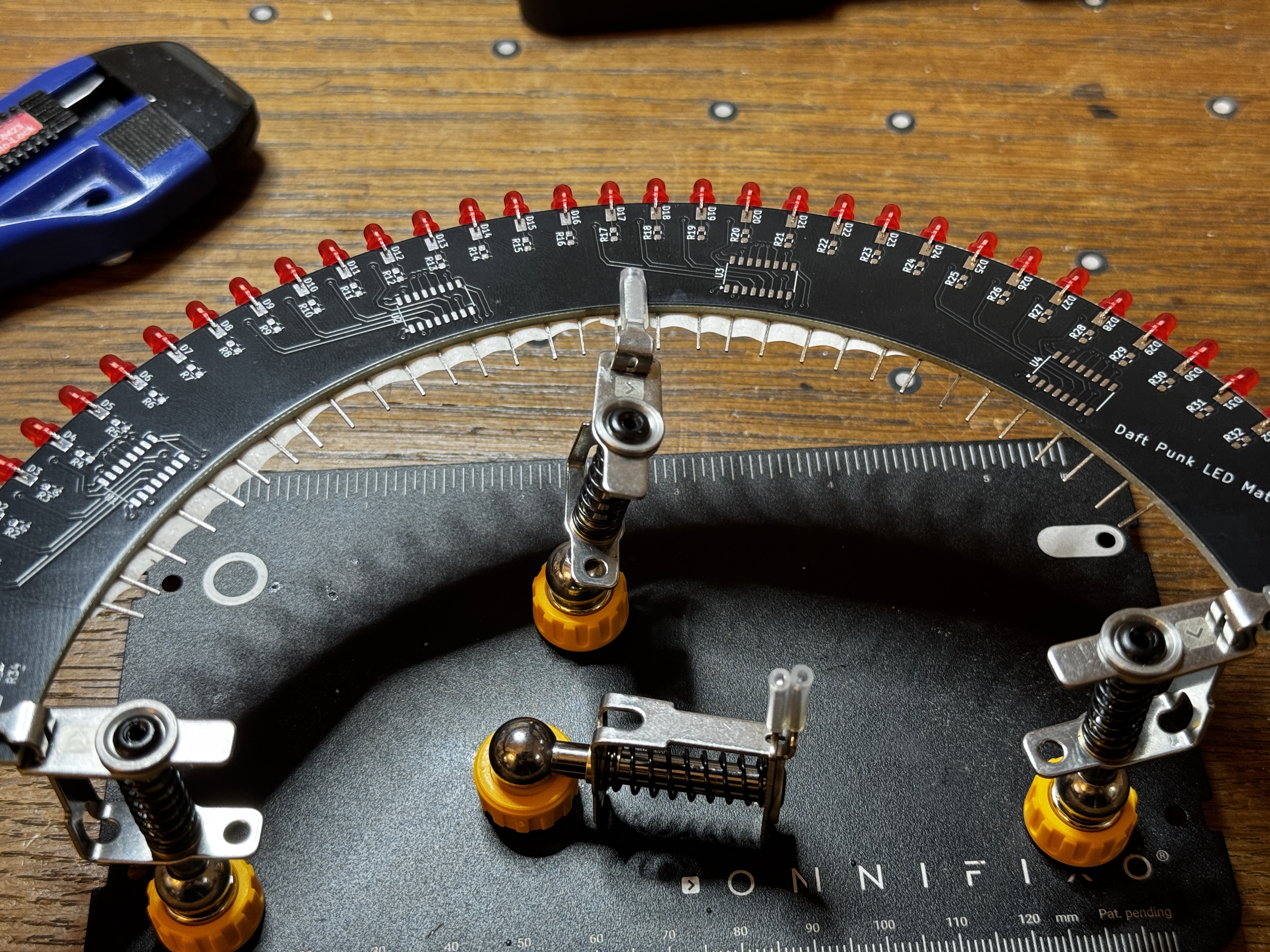
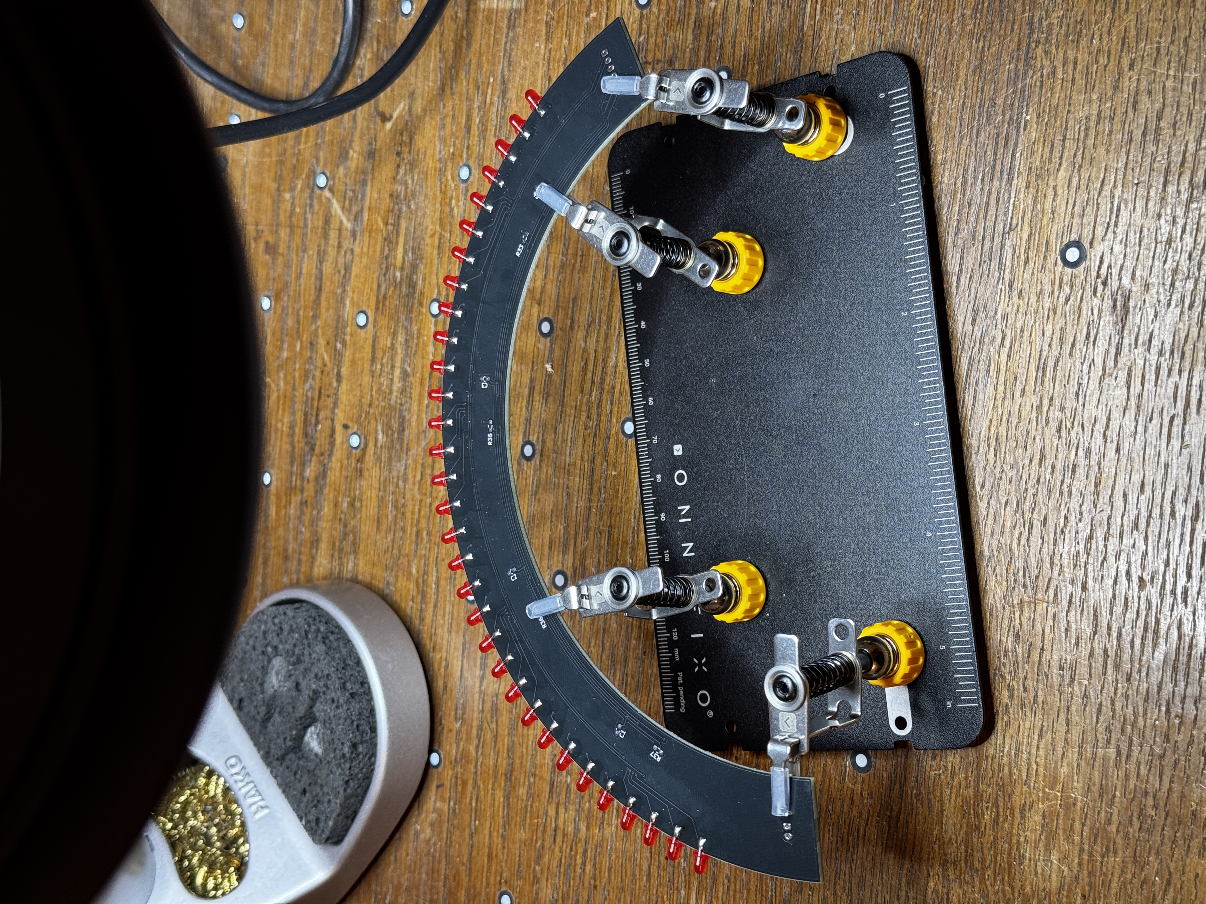
4. Prototype Boards Link to heading
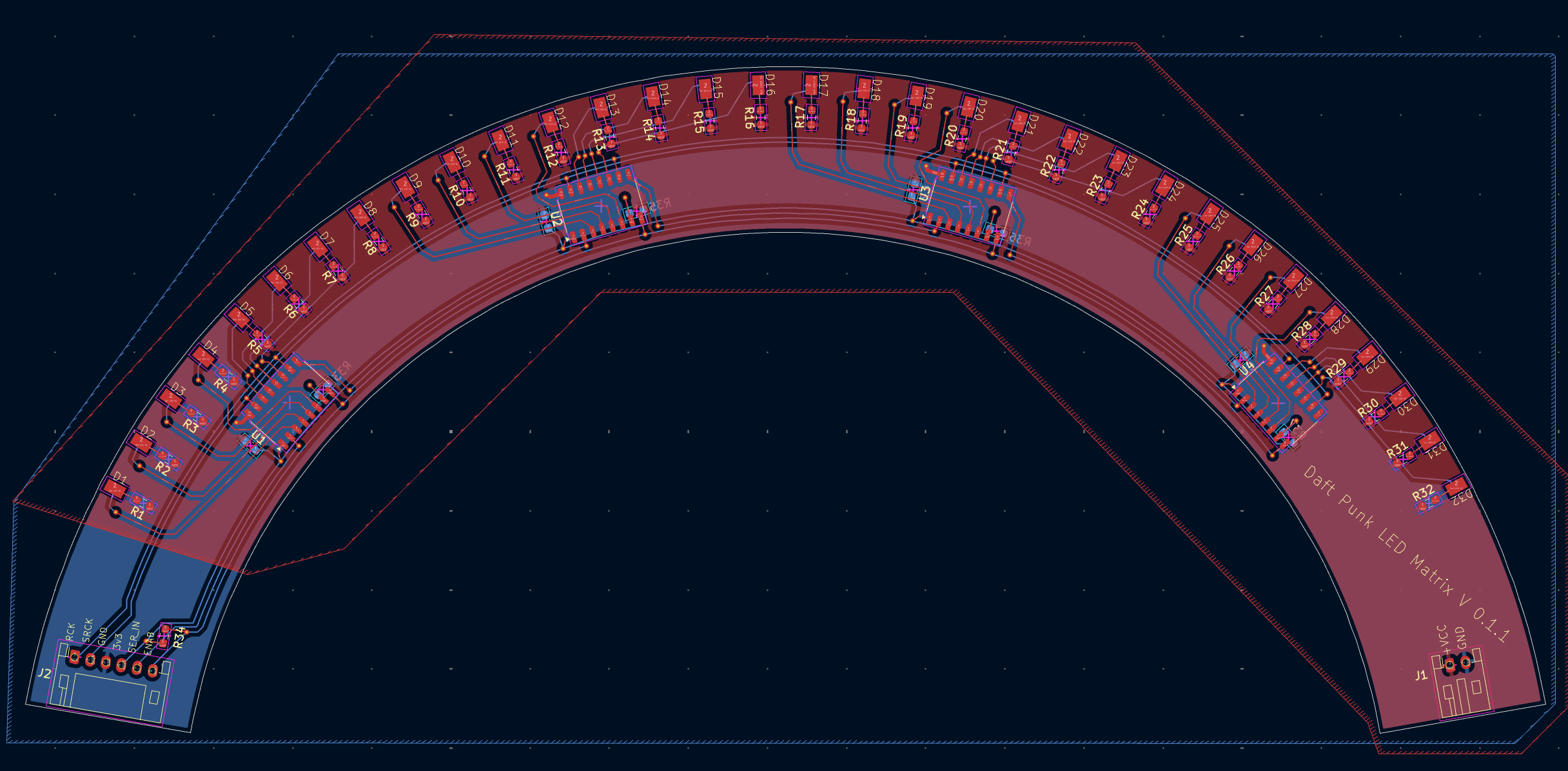
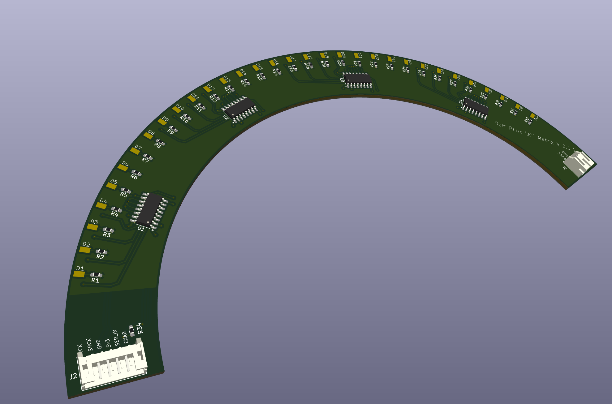
One of the things that I first thought about when this project came together was the visibility out of the helmet. The rats’ nest of wires always worried me. And as I was thinking about a solution, it occurred to me that the pin spacing on a 3mm LED is basically the same as the thickness of standard FR4 PCB boards - 1.6mm. So my idea was to edge-mount the LEDs and let the PCBs do the hard work of distributing power. It would also allow me to use SMD components which are lower profile and cheaply available as cut tape from DigiKey
Custom Footprints Link to heading
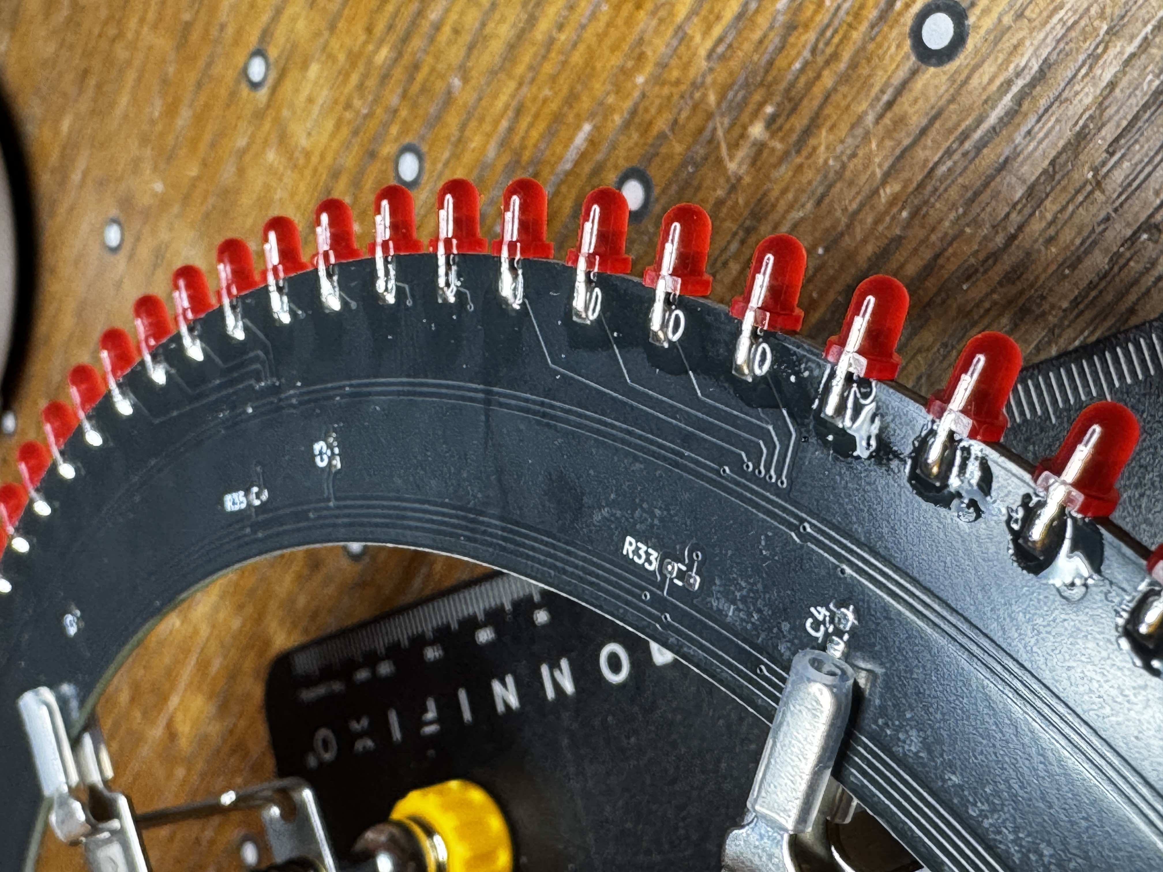
Getting this to work involved creating a custom footprint for the LED components, and placing them on the edge of the board. You can see what that layout looked like here. It’s extremely time consuming to place components in a radial pattern in KiCad.
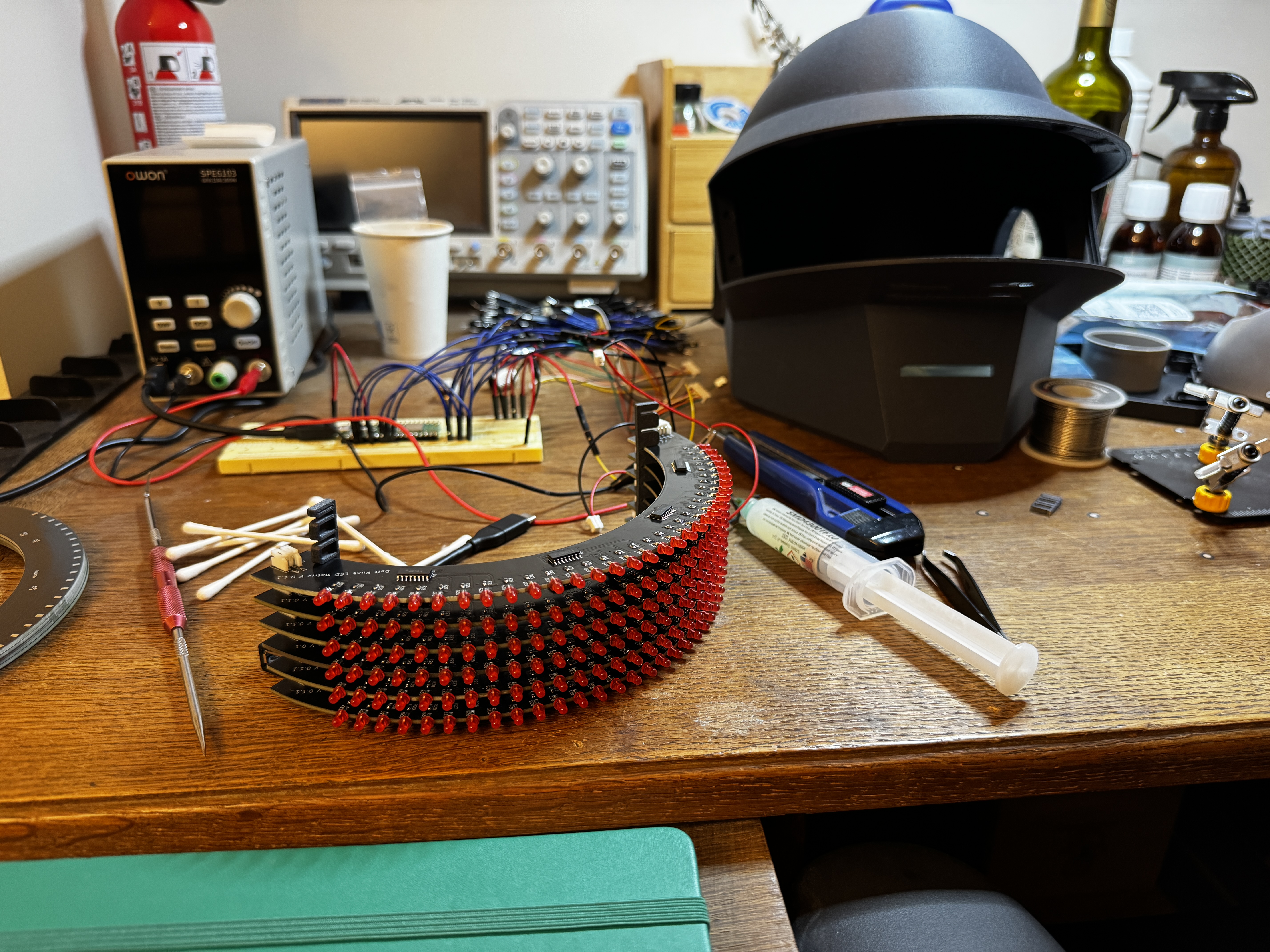
Assembly Link to heading
To assemble the boards, I first trimmed the positive terminal of the LEDs so that it landed directly on the pad. Then from the back of the PCB, I taped the negative terminal down so that they wouldn’t move. That meant that I could solder each individual LED down to one side of the board without it moving. After that, I trimmed the excess off the negative terminal, soldered them down, and cleaned up the flux.
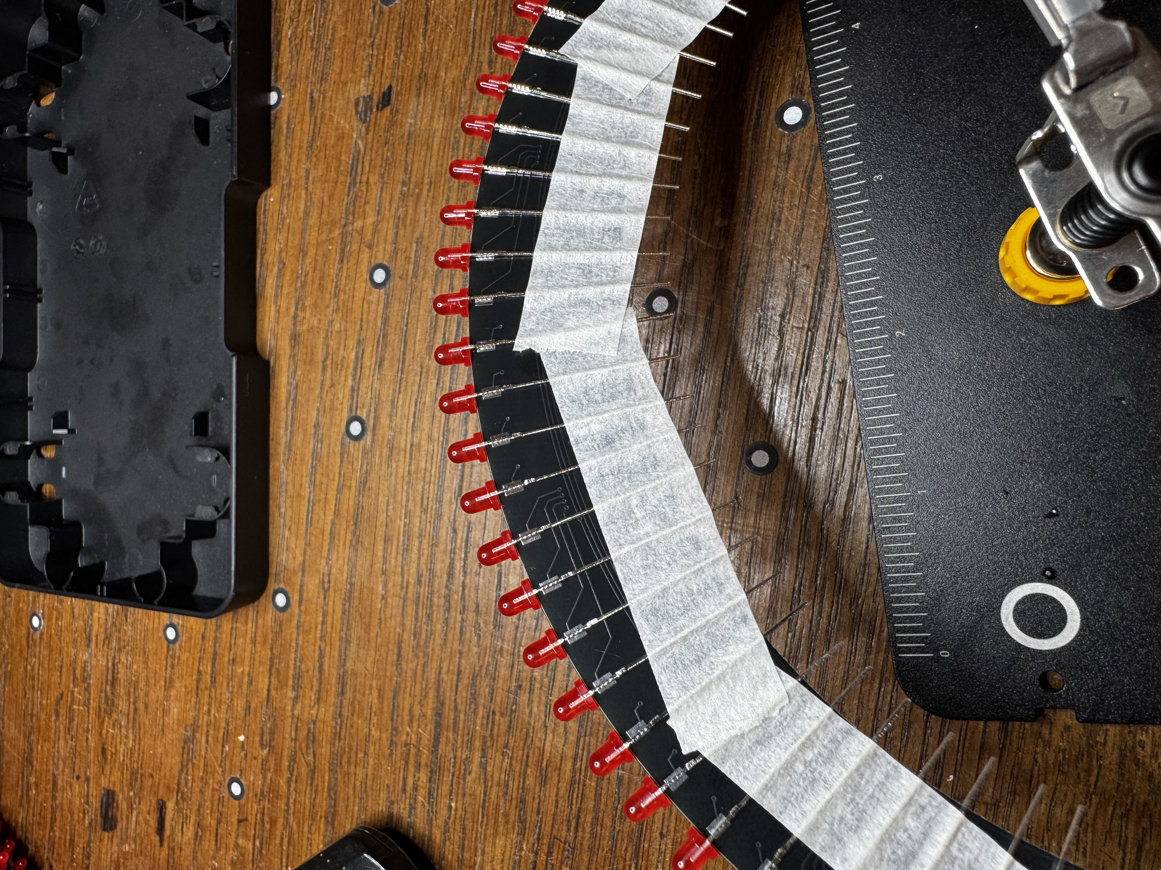
The SMD components were a lot more effort. I had to hand solder each one of them, and when I was ordering the parts, I think I underestimated just how small they are. I ended up using a pair of tweezers, and relying on the solder flux to hold the parts in place while I soldered them.
I verified that the LEDs and resistors were installed correctly with a multimeter, and that I was seeing the correct resistance values between +V and ground. All told, it took about an hour to an hour and a half to assemble each board on its own. So I spent the better part of three days assembling these in the hours after dinner.

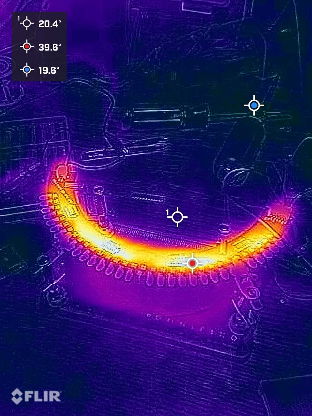
5. Thermals and Power Consumption Link to heading
I was curious if I had selected the correct resistors so I took a few thermal images of the board when it was running at full power. At 100% duty cycle, each board warmed up by a few degrees, mostly because the ICs were at their limit. But once they were running at their designed duty cycle, they barely warmed up at all.
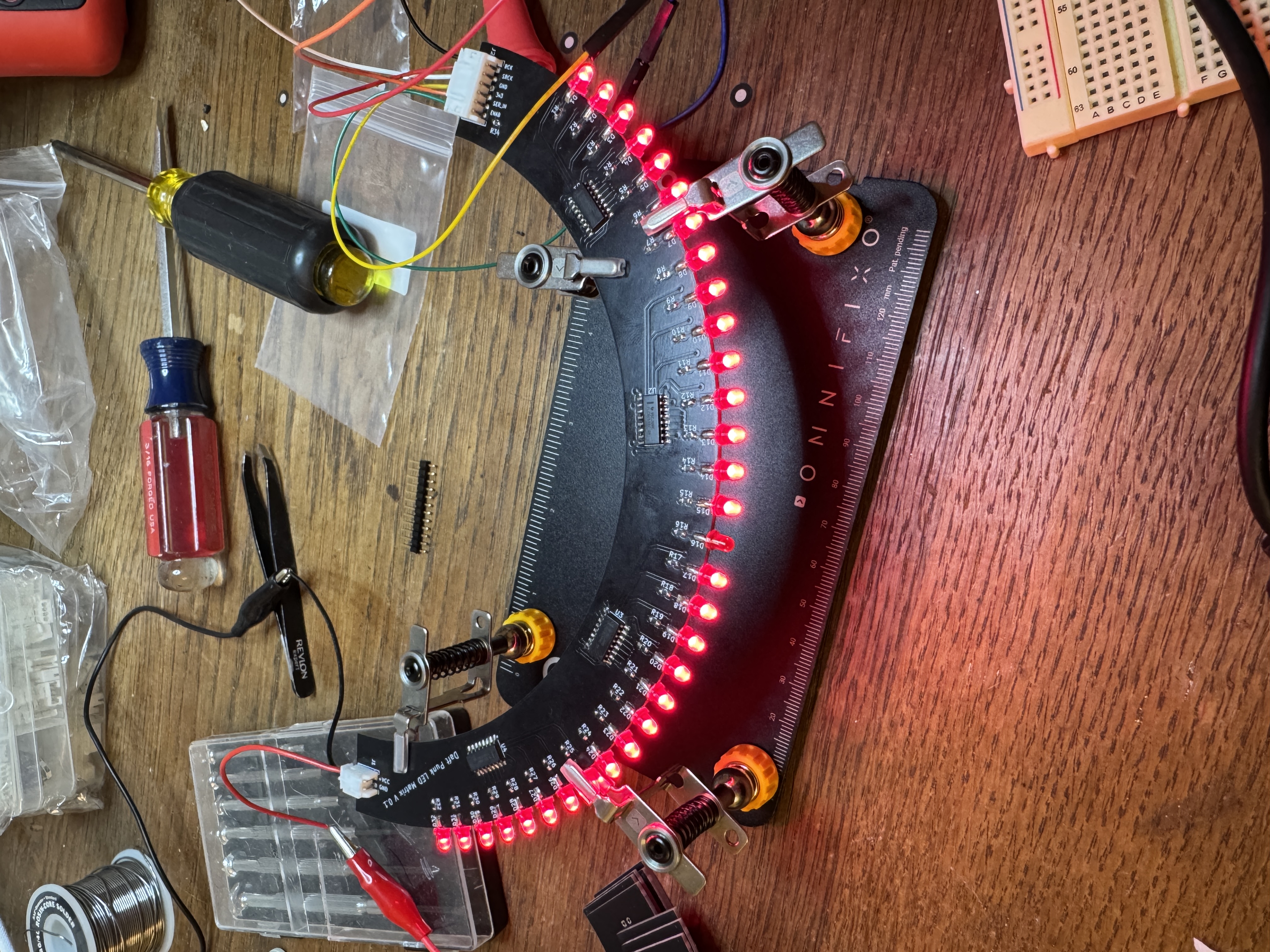
6. Firmware Iteration Link to heading
I spent a lot of time iterating on the firmware, and learned more in the process than any other part of this project. Embedded development is something I’m relatively new to — I’ve written plenty of Python, but I was unsure how it would translate to the RP2040.
What follows is the sequence of steps I went through to get from bare boards to a Bluetooth-controlled animated display. The full source is on GitHub if you want to play with it yourself.
Vanilla Python Loop Link to heading
Initially, I was handling communication with the board by bit-banging in a python loop. With every loop, I would update each row of the display with new bits, enable them for some delay, and then switch them off again. But it quickly became obvious to me that the strategy wasn’t going to work. Python and the pico havve a lot going on in the background, so the timing wasn’t precise enough to give me reliable multiplexing without visible artifacts in the display.
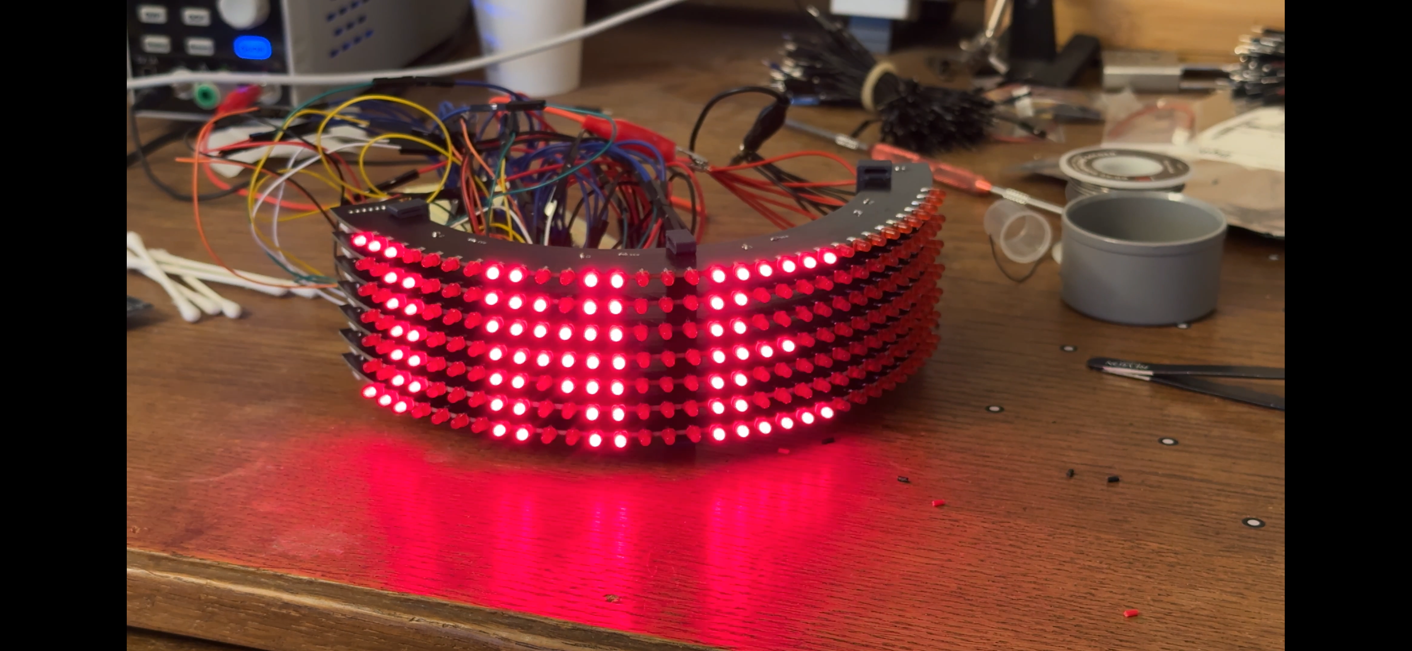
Switching to Programmable IO Link to heading
The RP2040 has a number of interesting features, one of which is its Programmable IO blocks. In a nutshell, what they enable you to do is write very precisely-timed routines in a small assembly language and hand them off to separate processors on the chip. That frees the main CPU up to do other things, like handle wireless communication or perform operations on frames before displaying them. So I rewrote the display refresh loop using PIO in a tightly controlled loop, and it really improved the flicker situation.
The implementation uses two coordinated state machines running at 2 MHz. The first (_shift_out) handles serial data — it pulls 32 bits from its FIFO, shifts them out to the TLC6C598 chain one bit at a time, and pulses the latch pin when it’s done. The second (_row_ctrl) handles row sequencing — it disables all rows, signals the data machine to shift, waits for confirmation, then enables one row at a time for a fixed dwell time before moving on. The two machines hand off to each other using IRQ flags, which guarantees that a row is never enabled while data is still being shifted into the registers underneath it.
@rp2.asm_pio(out_init=rp2.PIO.OUT_LOW, sideset_init=rp2.PIO.OUT_LOW, set_init=rp2.PIO.OUT_LOW, out_shiftdir=rp2.PIO.SHIFT_LEFT)
def _shift_out():
    """Clock out 32 bits, latch, signal row SM."""
    wrap_target()
    wait(1, irq, 1)         .side(0)   # Wait for row SM: rows disabled
    pull(block)              .side(0)   # Get column data from FIFO
    set(x, 31)              .side(0)   # 32-bit counter
    label("bitloop")
    out(pins, 1)            .side(0)   # Data out, SCK low
    jmp(x_dec, "bitloop")   .side(1)   # SCK high — rising edge clocks shift reg
    set(pins, 1)            .side(0)   # RCK high — latch
    set(pins, 0)            .side(0)   # RCK low
    irq(0)                  .side(0)   # Signal row SM: latch done
    wrap()

@rp2.asm_pio(out_init=(rp2.PIO.OUT_HIGH,) * 8, out_shiftdir=rp2.PIO.SHIFT_RIGHT)
def _row_ctrl():
    """Cycle row enables in lockstep with data SM."""
    wrap_target()
    pull(block)                        # Get row pattern
    mov(pins, invert(null))            # All rows disabled
    irq(1)                             # Signal data SM: safe to shift
    wait(1, irq, 0)                    # Wait for data SM: latch done
    out(pins, 8)                       # Enable one row
    set(x, 7)
    label("delay")
    jmp(x_dec, "delay")        [31]    # 8 × 32 = 256 cycles ≈ 128 µs at 2 MHz
    wrap()
Adding DMA Link to heading
The next step was to add direct memory access, which made it possible for the PIO state machines to fetch frames directly from memory without CPU involvement at all. This meant creating a double-buffer — two 8×32-bit framebuffers, one that the DMA reads continuously and one that the CPU writes to freely. When a new frame arrives, the CPU copies the back buffer into the front buffer using single 32-bit mem32 writes, one per row. Doing it this way means the DMA either reads the old value or the new one for any given row, never something in between. The CPU’s only job from that point on is to keep the back buffer filled and signal when a new frame is ready to be swapped in.
def swap(self):
    """Make the back buffer visible.

    Copies the back buffer into the front buffer while PIO and DMA
    continue running uninterrupted. Each 32-bit mem32 write is a
    single atomic bus transaction, so DMA always reads a complete old
    or new value per row — never a partial update.
    """
    src, dst = self._back, self._front
    for i in range(8):
        mem32[dst + i * 4] = mem32[src + i * 4]
Adding Bluetooth Link to heading
Adding Bluetooth was another one of those areas that I didn’t have a whole lot of experience with. The Pico W’s wireless stack runs alongside application code, which means you need some way for tasks to communicate with each other without blocking the rest of the firmware. To make this easier, I used some local coding agents to help me understand how asyncio is used in MicroPython for exactly this purpose. It’s really impressive what’s possible with an open-source languge model these days. (As an aside: I really do think local LLMs are a big part of the future of software engineering. But that’s a post for another time.)
The firmware advertises as “LEDMatrix” over BLE using a custom GATT service with two characteristics. The RX characteristic accepts 32-byte frame writes from a client — 8 uint32 values, one per row. The TX characteristic sends status back: connection state, a running frame count, and an error code if something went wrong with a write. Four asyncio tasks run concurrently: peripheral_task manages advertising and connection lifecycle, rx_handler_task waits for incoming frame writes and validates them, frame_applicator_task watches for new frames and applies them to the display buffer, and demo_task runs fallback animations whenever no client is connected. All of them share a DisplayState object that carries the current connection state and a frame event, so tasks can signal each other without polling.
async def main():
    data_sm, row_sm = create_state_machines()
    matrix = LEDMatrix(data_sm, row_sm)
    matrix.start(constants.TEST_PATTERN_ALL_ON)

    state = DisplayState()
    rx_char, tx_char = register_services()

    await asyncio.gather(
        peripheral_task(state, rx_char, tx_char),
        rx_handler_task(state, rx_char, tx_char),
        frame_applicator_task(matrix, state),
        demo_task(matrix, state),
    )
Adding Client-Side Features Link to heading
To interact with it, I added a client-side Python library. I wanted something I could use inside a Jupyter notebook for experimenting, but that could also be dropped into an automated routine running on some other device — a laptop on my desk, a Raspberry Pi zero in my backpack, a phone, or whatever.
The library is built on bleak, an async BLE library for Python. The top-level LEDMatrixClient class wraps a BleakClient as an async context manager, so connecting and disconnecting is handled automatically. The core method is send_frame, which packs the 8 uint32 values into 32 bytes and writes them to the RX characteristic. There’s also read_status and a notification subscription for the TX characteristic for monitoring what the firmware is seeing.
On top of that there are a handful of higher-level modules. frames.py handles conversion between the 32-byte format spoken by the firmware and a more human-friendly 8×32 grid of bits. text.py renders ASCII text into column data using a full 8×8 bitmap font, and includes a scroll_text function that slides the result across the display frame by frame. animations.py has a few built-in effects — blink, row scan, column scan, and a left-scroll — that just call send_frame in a loop. The whole thing is usable from a notebook with a few lines of code.
async with await LEDMatrixClient.connect() as matrix:
    # All LEDs on
    await matrix.send_frame([0xFFFFFFFF] * 8)

    # Scroll some text
    await scroll_text(matrix, "DAFT PUNK", delay=0.05)

    # Check what the firmware sees
    status = await matrix.read_status()
    print(status)  # {'connected': True, 'frame_count': 42, 'last_error': 0}
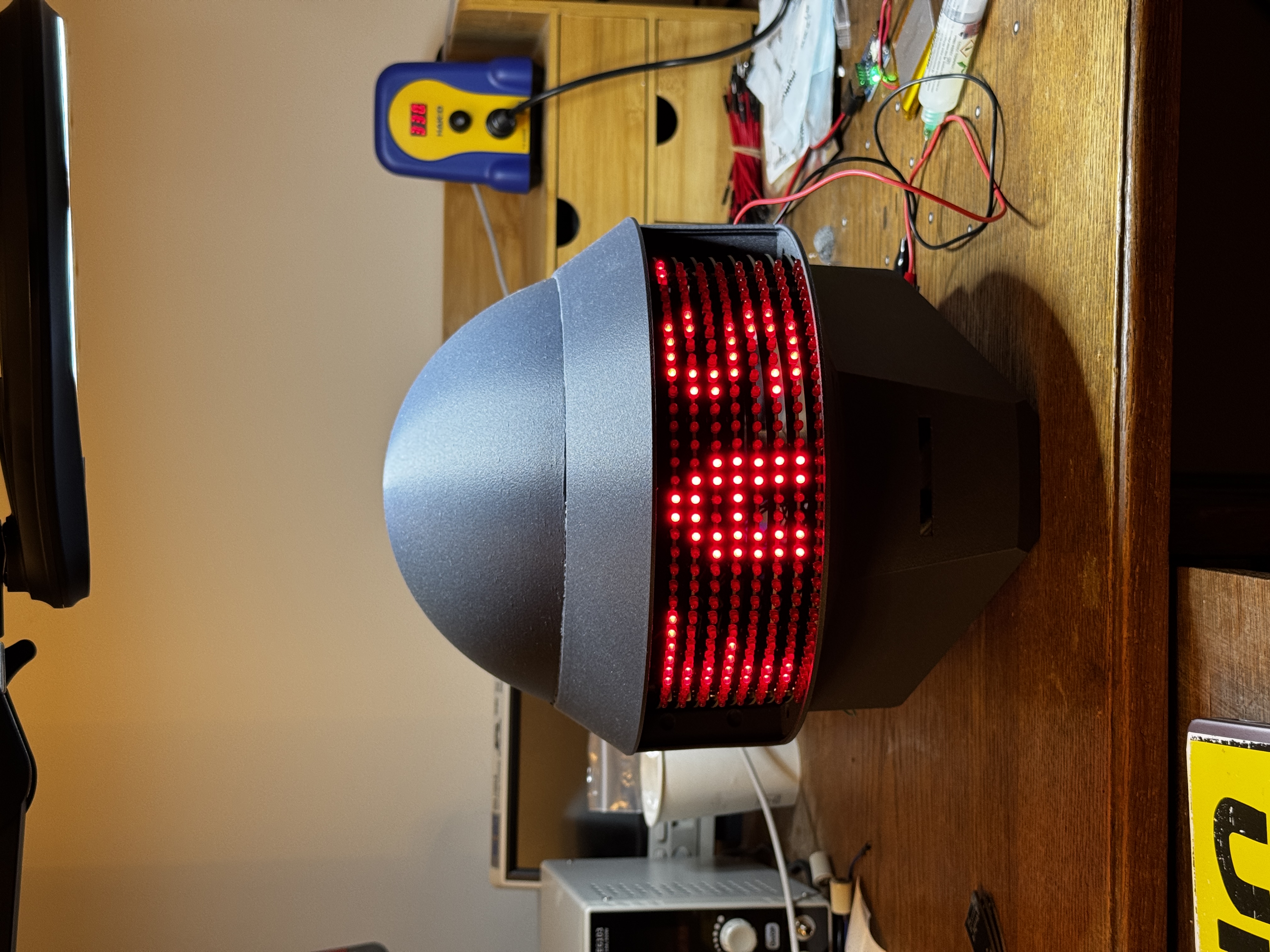
Demos and Default Features Link to heading
When the Pico isn’t connected to any client device, I still wanted it to be doing something interesting. A helmet sitting in the corner that just glows a static pattern isn’t very fun. So I expanded the demo task into a proper sequence of animations that cycles indefinitely — each one checking state.connected on every frame so it can hand off to a BLE client immediately on connection.
The sequence combines a mixture of animations and Daft Punk lyrics and rotates through them continuously:
async def run_demo(matrix, state):
    while True:
        if state.connected:
            await asyncio.sleep_ms(200)
            continue

        await _scroll_text(matrix, state, "HARDER BETTER FASTER STRONGER")
        await _sparkle(matrix, state)
        await _scroll_text(matrix, state, "AROUND THE WORLD")
        await _column_sweep(matrix, state)
        await _scroll_text(matrix, state, "ONE MORE TIME")
        await _row_wipe(matrix, state)
        await _diagonal_cascade(matrix, state)
        await _invert_pulse(matrix, state)
async def _sparkle(matrix, state, duration_ms=3000, delay_ms=80):
    steps = duration_ms // delay_ms
    for _ in range(steps):
        if state.connected:
            return
        frame = [random.getrandbits(32) & random.getrandbits(32) for _ in range(8)]
        matrix.set_framebuffer(frame)
        matrix.swap()
        await asyncio.sleep_ms(delay_ms)
7. Choosing a Power Source Link to heading
Power distribution was a tough decision. I needed something simple, compact, and capable of supplying enough current to run both the display and the Pico. I went back and forth on a few options and seriously considered designing my own board — that would probably have been the cleanest solution. But it also represented a significant amount of extra work, and there are off-the-shelf options cheap enough to make that hard to justify. I ended up going with a Seeed Studio LiPo Rider Plus. It can deliver 2.4 A at 5 V, which is more than enough headroom for what I need. It takes 3.7 V lithium cells via JST-PH — a connector I have in abundance — and includes USB charging, a power switch, and a charging indicator LED. Five bucks, no custom PCB required.

I have yet to test the battery life. But I’m confident that it’ll last at least a couple of hours on a full charge. And this battery is small enough that if I need to, I can add more capacity without that much extra effort.
8. Next Steps Link to heading
The prototype boards are assembled. Now I need to install them in the helmet. A lot stands in my way.
Logic and Power PCBs Link to heading
The prototype uses the Pico W sitting loose on a bench connected to the row boards by jumper wires. That’s not going to fit inside a helmet. The plan is to design a dedicated logic board that mounts the Pico, handles the JST-PH bus connections, and routes cleanly to the matrix — and a separate power board that handles the distributing power to the LEDs. The Seeed Studio battery board handled a lot of the power delivery needs, but I need to think intelligently about the right way to integrate it with the display. And, somewhat unsurprisingly, I’m hearing a bit of switching noise from the multiplexing loop that I’d like to try tuning out with decoupling capacitors in the power circuit. Not sure where that will lead me, but it’s on my mind.
More Clever BLE Behavior Link to heading
Right now the BLE interface is essentially a raw frame pipe — you send bits, they appear on the display. There’s a lot of room to make that more interesting. I’d like to add audio-reactive animations driven from a microphone, or maybe some kind of sync mode with a client device running elsewhere. None of that requires hardware changes, just firmware and client work.
Electroplating Link to heading
This is still the most uncertain part of the whole project. The small-scale tests on smaller components have been encouraging, but scaling up the plating bath to cover a full helmet is a different problem. I need to sort out the chemistry volume, the electrode geometry, and the polishing process before I’ll have anything worth photographing. More on that when I get there.
Lexan Link to heading
The visor opening also needs a lens. The plan is to cut a piece of Lexan to fit, apply window tint film to get the right level of see-through darkness, and figure out a clean way to retain it in the frame. Simple in theory but I’ve got no idea what it’ll look like in practice.
This is part 3 of an ongoing build log. Part 1 covers the plan; Part 2 covers the printed shell.